Whether you’re an electronics engineer, a lighting product designer, or a purchasing manager sourcing boards for the first time, understanding LED PCB manufacturing will help you to get smarter, more reliable LED products. This guide covers everything — from materials and design to assembly, testing, and finding the right manufacturing partner.
What Is LED PCB Manufacturing?
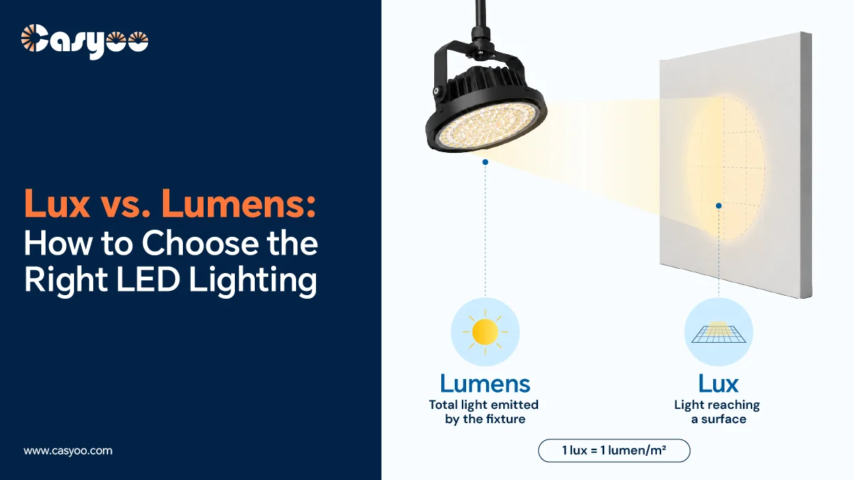
LED PCB manufacturing refers to the design, manufacture, and assembly of printed circuit boards specifically designed to house, connect, and power LEDs. These circuit boards differ from standard PCBs. They are widely used in modern LED lighting systems, such as LED grow lights, LED street lights, ultra-thin panel light panels, floodlights for stadiums and other customized commercial lighting fixtures. Because LEDs convert a small portion of electrical energy into visible light and the remainder into heat, LED PCBs require greater attention to thermal management, the use of metallic components, and the application of special electroplating processes. LED PCB design must ensure efficient heat dissipation while maintaining electrical reliability; otherwise, LEDs will age rapidly and experience color shifts. This is why MCPCBs are a commonly used material for LED PCBs among many PCB materials. LED PCB manufacturing is not only a discipline of electronic engineering but also a discipline of thermal engineering.
Key Materials Used in LED PCB Manufacturing
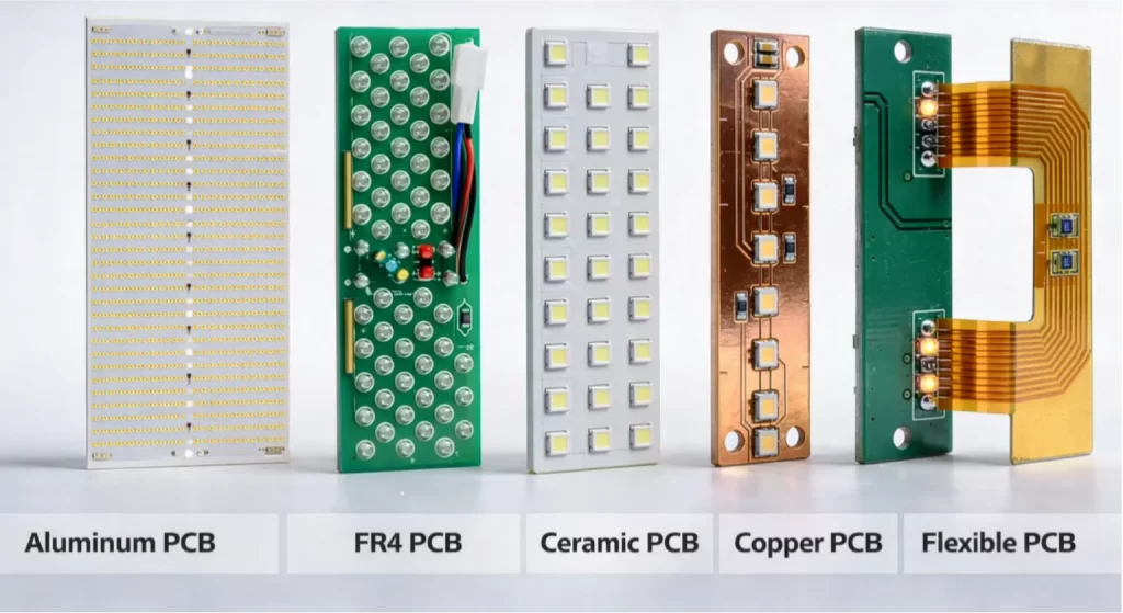
The substrate material of LED PCB is the single most important factor affecting thermal performance, flexibility, and application suitability. Here’s a comparative look at the most commonly used materials:
| Material | Type | Best For |
| Aluminum | Metal Core (MCPCB) | High-power LED lights |
| FR4 | Standard Fiberglass | Low-power / decorative LEDs |
| Ceramic | Advanced Ceramic | Automotive, industrial |
| Copper | Metal Core (MCPCB) | Ultra-high-power systems |
| Flexible (Polyimide) | Flex PCB | Wearables, curved lighting |
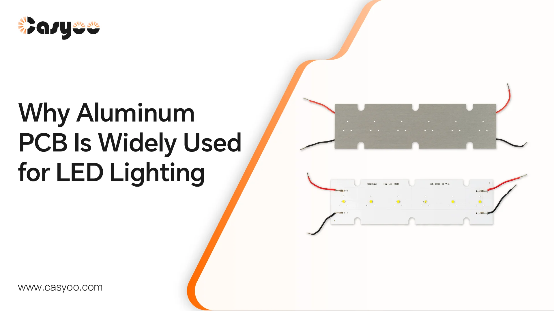
Aluminum PCB
Aluminum PCBs are commonly used in LED lighting. Its feature is good thermal conductivity, which can lead to fast heat dissipation from LEDs. This substrate material is commonly used in LED streetlights, floodlights, bay lights, and grow lights. For many OEM/ODM lighting projects, aluminum-based PCBs achieve a good balance between performance and cost, making them the preferred choice for large-scale commercial production.
FR4 PCB
In standard PCBs, FR4 PCBs are a conventional glass fiber reinforced material that is commonly used. In LED PCBs, they are generally applied to lower-power or less cost-sensitive applications, including control circuits and indicator lights in low-power LED modules. They do not have a very good heat dissipation efficiency as compared to metal and ceramic materials, and thus cannot be used in the high-efficiency lighting system. Nevertheless, they are the least expensive and simplest to handle and hence a cost-effective choice in case of necessity.
Ceramic PCB
The application of ceramic PCBs is characterized by the need to have high thermal conductivity and high electrical insulation. They perform particularly well in illuminating conditions with a very high heat dissipation and durability requirements. The ceramic base is more resistant to high temperatures and more dimensionally stable than the normal PCB materials thus it is commonly used in the high-performance LED modules, car lights, UV lights and other specialty uses. But one disadvantage of this material is that it is more expensive and has a complicated production process. It is better suited to serve buyers who need high-end or highly specialized lighting products.
Cooper PCB
In some LED PCBs, we choose copper-based PCBs. They offer superior thermal conductivity and strong current carrying capacity, making them suitable for high-power LED applications with extremely stringent heat dissipation requirements, such as tower crane lights and industrial mining lamps. Copper-based PCBs are heavier and more expensive than aluminum-based or FR4 PCBs, and are generally more difficult to manufacture, thus their use is less common.
Flexible PCB
The fifth material that we are going to talk about is flexible PCBs. Flexible PCBs are specially made to support LED lighting, which needs to be bent, deformed and installed in space-restricted spaces. This material is often used in LED strips, decorative lighting, backlighting systems, and a few custom lighting components. Although it is not the most suitable option for applications that require high power and heat dissipation, it is highly useful in applications that prioritize form factor adaptability, thinness, and assembly flexibility. Flexible PCBs may prove to be a good solution in custom OEM LED lighting that require product form factor to be a key consideration.
Choosing the Right Material for Your Project
After introducing the differences among these five materials, you must have more understanding of how to choose a suitable material for your lighting project. The choice depends on your power rating, thermal management needs, product structure and budget. For OEM/ODM projects, it always needs to evaluate materials together with the application. Casyoo is able to recommend the most suitable solution based on technical performance and actual production needs.
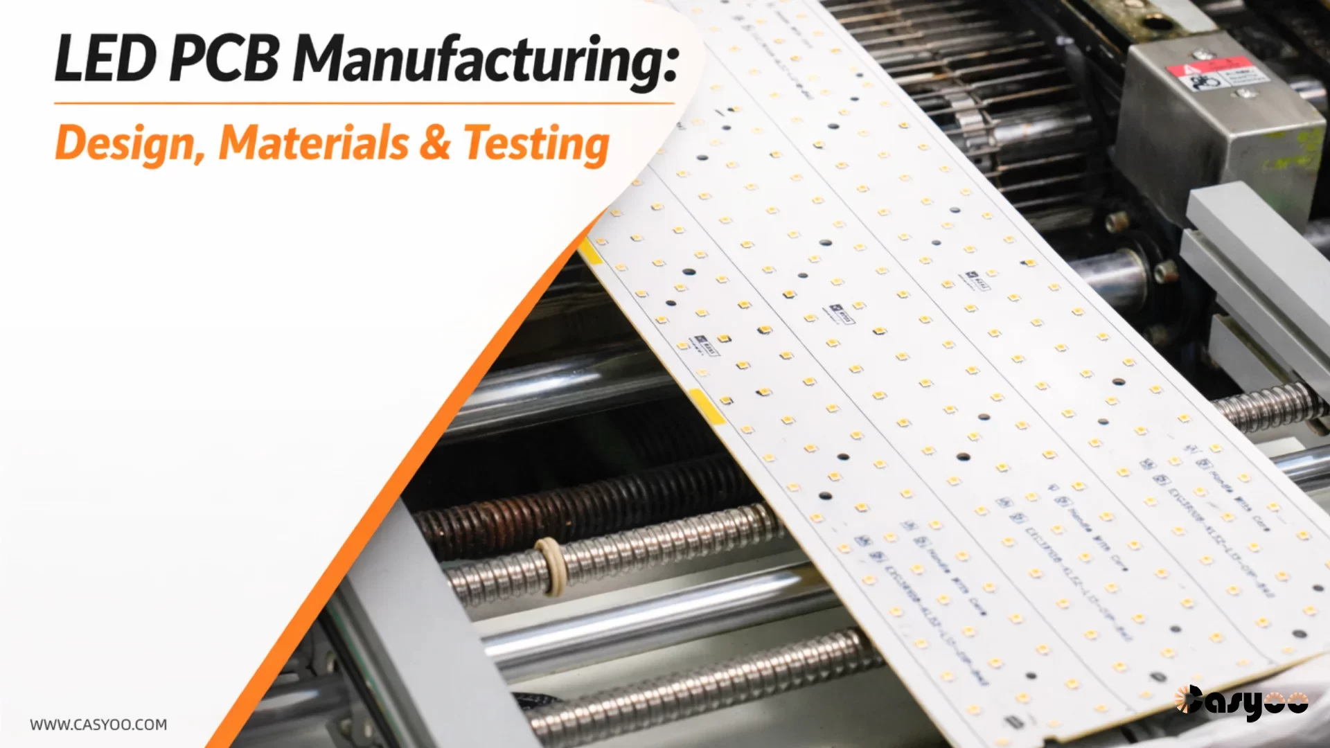
Key Process Steps of LED PCB Manufacturing
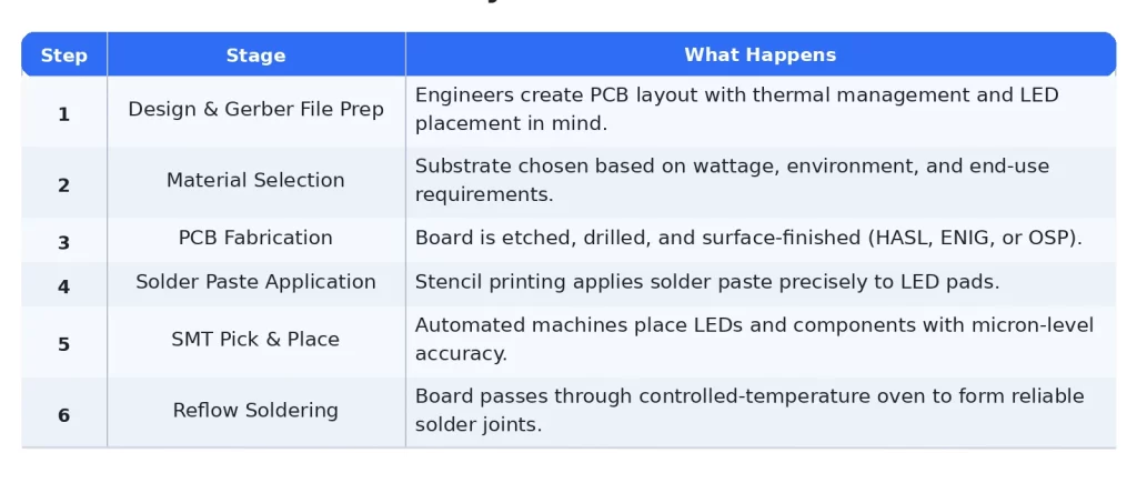
Understanding the key process steps of LED PCB manufacturing can help you evaluate suppliers more confidently and make better decisions for your lighting project. Although the specific sequence of steps might differ based on the type of board, power level, and use, most of the LED PCBs follow a comparable manufacturing process- engineering approval to fabrication, assembly, inspection and delivery.
Step 1. Design File Review & Pre-Production Engineering
Before we start, we need to review the design files and production requirements. In this first step, the manufacturer will check the Gerber files, BOM, drill data, board dimensions, and component layout. LED PCB design really matters in the PCB manufacturing process. The thermal paths, copper layout, pad design, and LED spacing can all affect product heat dissipation and final product performance. A careful engineering check helps identify possible issues early and reduces the risk of problems in later production.
Step 2. Bare PCB Fabrication
After we confirm the design, the selected substrate will be processed into a bare PCB. This step usually includes drilling, circuit imaging, etching, plating, solder mask application, surface finish treatment, profiling, and electrical verification.
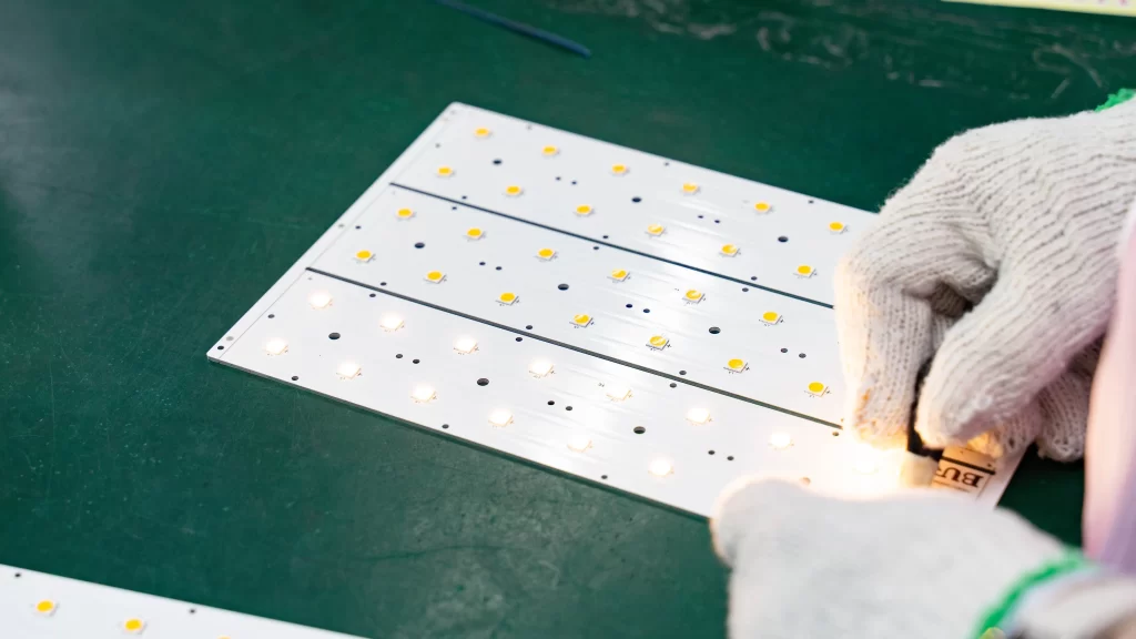
Step 3. PCB Assembly via SMT Processing
After the bare PCB is completed, we will move to the SMT assembly process, where the board becomes a functional LED module. This step typically includes solder paste printing, automated pick-and-place, and reflow soldering. The following chart gives a clearer look at how SMT processing turns a bare PCB into a functional LED module.
Since the LED products need a stable light output and good thermal balance, assembly quality is very essential. Even minor mistakes during placement or soldering may affect consistency, reliability and product life. The process chart here may help you to describe each SMT assembly step in a more direct manner graphically.
Step 4. Inspection & Testing
Once assembled we will inspect and test the board. This will guarantee that the quality and functionality work well. The stages can involve AOI, X-ray examination (if necessary), electrical examination, and functional testing.
For LED PCB, the manufacturers may also test the light, voltage, and current draw, and the general operating stability. With the help of these tests, the defects will be determined before delivery and the probability of on-site failure in real lighting projects is reduced.
STEP 5: Final Finishing and Delivery
The final QC, cleaning and packaging, and shipment preparation processes are conducted on the completed boards in the last step. This step may also include labeling, custom packing or other special handling of OEM and ODM orders depending on the project.
Proper finishing and delivery process would facilitate maintaining the boards arrive in good condition and are ready for integration into the final lighting product.
Testing and Quality Control in LED PCB Manufacturing
As we mentioned above (the PCB manufacturing process), testing is the step that turns a manufactured board into a reliable product. The most commonly used QC techniques in professional production are these:
- Automated Optical Inspection (AOI): Board scan cameras are used to detect missing parts, solder bridges, and misalignments – defects are detected at a high rate.
- X-Ray Inspection: This is necessary in BGA and chip-on-board (COB) LEDs in which the solder joints are concealed under the component. X-ray can give voids and cold joints which cannot be seen by AOI.
- In-Circuit Testing (ICT): This is where electrical probes are used to test all the nodes on the board to ensure the proper values of the components and connectivity.
- Thermal Resistance Testing: Tests the actual junction-to-board thermal resistance, ensuring that the PCB will work with its rated thermal requirement in actual application.
- Lumen Output & Binning Verification: To ensure that LED luminous flux and color temperature ( CCT ) are within specifications.
- Aging Test: Boards are then tested over long durations (usually 24-48 hours) to determine failure early in life before delivery.
How to Choose the Right LED PCB Manufacturing Partner
Not every supplier provides the same level of support. Some manufacturers just produce bare boards and others have the capability of encompassing the entire process from engineering review to assembly and integration of final products.
These are some factors that you should check in case you are sourcing an OEM or ODM lighting project.
- Certifications: For established quality and safety requirements, choose manufacturers that recognize standards like ISO 9001, UL, RoHS and IPC Class 2/3 compliance.
- Experience: A supplier with 5+ years of experience in LED PCB or a lighting-specific application is generally better suited to face thermal design, assembly issues, and customer-specific requirements.
- Thermal Testing: Check whether the manufacturer can provide verified thermal resistance and junction temperature figures, particularly in high-power LED lighting projects.
- Prototyping: Ask if they offer quick-turn prototypes within 24–72 hours, as they can be used to accelerate validation and product development.
- Communication: In most cases, good manufacturers will offer a dedicated engineer or account manager, who will help facilitate easier technical discussions and project coordination.
- Lead Times: Find clear production schedules and transparent lead times, preferably with tracking or frequent progress reporting.
- Flexible MOQ: For a new product development or making early-stage orders, it is convenient to deal with a supplier that offers low MOQ for startups, R&D team, or pilot run options.
LED PCB manufacturing is not just a production step hidden inside a lamp. It is among the fundamental elements that determine the quality of products, thermal performance, and reliability in the long-term.
Every step in the selection of the material and board design to SMT assembly and testing will affect the final product. For B2B light buyers, this is a process that can be used to make more effective choices and risk management.
Need support for your next OEM or ODM lighting project? Get in touch with us to find out more about your designed LED PCBs, or see what we can offer in LED grow lights, street lights, and other commercial lighting needs.